![]() AyMINE – Technical documentation
AyMINE – Technical documentation
Modules
 Task, project & quality management
Manager approval with the task report
Why some data can't be deleted
Adminitration of areas, projects, calendars
Region / project / methodology
Change management process in a project
GDPR and record of qualifications
Qualification of user or contact
Right to Manage Qualifications
Failure Analysis for an Individual Property of a Component or Process
FMEA – Probability of Detection
FMEA – Probability of Occurrence
Task, project & quality management
Administration of the Task Management Module
System rights for the task management module
Improvements and Preventive Measures
Methodology and Quality Management systems
What a methodology / QMS consists of
Problems, tickets and their management
Collaborative Resolution of Multiple Problems
Customer Service Response Generation
Incident and Quality Issue Management
Objects affected by the problem
Problems, Incidents, Helpdesk Tickets
Return project plan by baseline
Sample tasks and methodologies of the area
Effect of the task on the right to modify the attached object
The person responsible for the task
Working procedure – task definition
Objects related to the task pattern
 Contacts and directories module (CRM)
Order overview for customer groups
Contacts and directories module (CRM)
System Permissions and CRM Module Settings
Send bulk messages in compliance with GDPR
How to correctly forget a person's details
Unsubscribe and set preferences
for bulk mail
 Web management and automation
Receiving a message from the web
Human resources
Personalistics – User Permissions
Human Resources module security
Manage department / division data
Overview of Personnel Information for pracov# Employment Contract
Synchronizing staff and system users
 Products, assets and sales
Received order for goods or services
Finance management
Metrics and Measurements
Technical Modules
Sabre plugin module
Enterprise Architect connector
Database link to Enterprise Architect database
Enterprise Architect connector
System Modules
 The AyMINE Framework Module
AyMINE — Tips for Mobile Usage
Configure how your system looks and works
Gestures and Keyboard Shortcuts
More about how the system works
Private notes and tags for objects
Overview of Modules and Record Types
Filtering in the list of records
System Management
Additional functions with files
Copying and moving files between objects
Files (documents) linked to the object
Formatted texts in the application
Gateway settings for external messages
IMP gateway settings for email communication
Internet Call Gateway Settings
Message with the outside world
 FMEA Analysis Process
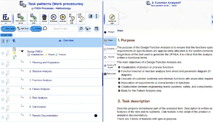
The FMEA analysis process consists of 7 steps
FMEA Methodology in AyMINE
AyMINE has a predefined methodology for the FMEA process (of course, you can modify it or create your own methodology).
You only need to generate a set of tasks based on templates in the methodology.
Overview of FMEA Steps
These sections do not describe the entire process but rather its implementation within AyMINE. For a complete understanding of FMEA, we recommend our training, and details are also described within the FMEA process itself. The goal of this page is to provide a global perspective on the process, which may not always be evident from individual tasks.
Step 1 - Planning and Preparation
FMEA preparation is guided by a standard FMEA process. The process can be initiated by the project manager or the product owner. It should be linked to the analyzed product or process. Its connection can be made both to a product already recorded in the product database and to analysis elements, such as a manufacturing process.
A key part of step 1 is defining the team that will conduct the FMEA analysis. The leader nominates team members for the analysis task, but not for the preparation task, which remains their responsibility.
The planning of further steps depends on the availability and size of the team:
- Responsibility for reviewing and possibly supplementing the analysis of the examined subject. The responsible worker receives the FMEA - step 2 task.
- Responsibility for preparing the functional analysis - FMEA - step 3.
- Inviting experts to a meeting for failure and risk analysis. It is necessary that they familiarize themselves with the analysis beforehand, so there should be enough time between completing steps 2 and 3 and starting step 4 (the time depends on whether independent experts unfamiliar with the subject are involved).
Another important part is planning the analytical meetings where steps 4 and 6 will be carried out.
A high-quality plan and preparation may seem partly obvious and partly unnecessary. However, thorough preparation determines whether the analysis will be effective.
- Clearly define the scope of the analysis, i.e., the exact boundaries of the analyzed subject (process, product).
- Assess who truly understands the topic and assemble a competent team.
- Plan the preparation, including the preparation of background materials and all other steps.
Step 2 - Structural Analysis
The output is the structure of the subject, either in the form of components (for a product) or process steps and used equipment (for a process).
If product analysis is used for structural analysis, the outputs can be visualized using Enterprise Architect. (This requires a connection via the eacon connector to the EA model.)
By using a documented component base, it is possible to build on an already existing previous FMEA analysis. Therefore, it is advisable to use already entered components whenever possible and not create duplicates in the structural analysis.
Step 3 - Functional Analysis
The output consists of descriptions of properties, operating modes, and states in detail for individual units. At the component level, the relevant properties for FMEA should be described. These descriptions are directly linked to the elements, so functional analysis can logically only be performed after structural analysis.
The primary tool for verifying functional analysis is fulfilling the functional specification of the product or process using properties (a general term including):
- General property
- Functionality
- Operating mode
If a repeated FMEA analysis of a component is conducted for another purpose, documentation from the previous analysis can be used, or a new analysis can be created for the same element. Therefore, it is possible to specify for each property which analysis it is included in. (If not specified, it is included in all.)
Step 4 - Failure Analysis
Possible failures are entered for each property. Failures can be recorded in bulk for each property, but it is better to list them individually as failure cases (tab in the detail view).
Possible failure cases become documentation for the property or component (or process step). These cases are further analyzed in step 5.
Each component and each property are recorded separately, so splitting FMEA analysis into multiple groups is not an issue if it makes sense based on different properties.
Note on permissions: The analysis can be conducted by those who are active collaborators in the area or project where the analysis is performed. At the same time, they must have permission to access the analyses. This allows for proper control over who participates in the analysis.
Documentation quality: We recommend that all those participating in the analysis be listed as team members for this task. The team composition is part of the analysis documentation, based on the list of participants. For meetings, organize discussions, where FMEA will be the only agenda item. This ensures that the meeting will focus solely on FMEA.
Step 5 - Risk Analysis
Risk analysis builds on failure analysis – it adds data to failure cases recorded in step 5 of the FMEA process. Essentially, new rows should not be added to the FMEA – they correspond to possible failures, and only those already identified will be examined.
Step 6 - Optimization
Like step 5, step 6 is based on the preparation from steps 2 and 3. For each failure and risk analysis, the system calculates the action priority for risk minimization. (The system also calculates the older RPN, as many teams are still accustomed to using this index.)
A critical part of optimization is designing changes that reduce the likelihood of failure. Each failure can be differentiated between current minimization tools and newly proposed measures.
New measures are documented in the analysis, and expected values are recorded – the analysis output is thus not only the current state but also the state after implementing all measures.
Tasks and Requirements for Resolution
Measures from the analysis are further reflected in change requests or tasks to address the problem. Both can be created directly in the failure case detail or the property detail. The request or task is created with a link to the potential failure, making it clear why the request or task was created and allowing tracking of whether it has been resolved.